![]()
Recent Articles
I’ve always wanted to implement an ATmega328P with an LCD screen as a replacement for a propriety one. I envisioned something more open to interface with and had USB connectivity. So one day browsing through Facebook Marketplace, I found someone selling a ThermalTake Bach for $10 with an LCD screen cutout. The case, of course didn’t have the LCD in there anymore, so my chance had arrived.

I then, naturally, reached for my breadboard and did a quick prototype to get everything working. Once complete, I then started on the firmware. Through a little trail and error, this is what I came up with:
#include <LiquidCrystal.h>
#include <ArduinoJson.h>

// Creates an LCD object. Parameters: (rs, enable, d4, d5, d6, d7)
LiquidCrystal lcd(12, 11, 5, 4, 3, 2);

// Due to char set issues, this will create the /
byte customBackslash[8] = {
  0b00000,
  0b10000,
  0b01000,
  0b00100,
  0b00010,
  0b00001,
  0b00000,
  0b00000
};

String incoming = "";
bool readingJson = false;

void setup() {

  lcd.createChar(7, customBackslash);

  Serial.begin(9600);

  // set up the LCD's number of columns and rows:
  lcd.begin(16, 2);

  // Clears the LCD screen
  lcd.clear();

  // Startup defaults
  lcd.setCursor(3,0);
  lcd.print("Booting...");
}

void flipper() {

  lcd.setCursor(1,0);
  lcd.print("/");
  delay(250);

  lcd.setCursor(1,0);
  lcd.print("-");
  delay(250);

  lcd.setCursor(1,0);
  lcd.write(byte(7));
  delay(250);

  lcd.setCursor(1,0);
  lcd.print((char) 0b01111100);
  delay(250);
}

void loop() {

  // A little animation!
  flipper();

  while (Serial.available() > 0) {
    char c = Serial.read();
    Serial.print(c);

    // Detect start/end of JSON (optional but helpful)
    if (c == '[') {
      readingJson = true;
      incoming = "";     // reset buffer
    }

    if (readingJson) {
      incoming += c;
    }

    if (c == ']' && readingJson) {
      readingJson = false;
      processJson(incoming);
    }
  }
}

void processJson(const String &jsonString) {

  // Allocate memory for JSON document
  StaticJsonDocument<256> doc;

  // Parse the JSON
  DeserializationError error = deserializeJson(doc, jsonString);
  if (error) {
    Serial.print("JSON parse failed: ");
    Serial.println(error.c_str());
    return;
  }

  // Loop through array entries
  for (JsonObject obj : doc.as<JsonArray>()) {

    int col = obj["col"];
    const char* data = obj["data"];

    if (col == 1) {
      lcd.setCursor(3,0);
      lcd.print(data);

    } else if (col == 2) {
      lcd.setCursor(0,1);
      lcd.print(data);

    }
  }
}
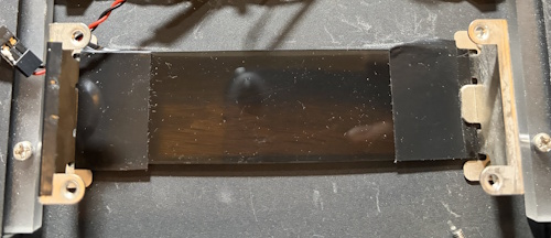
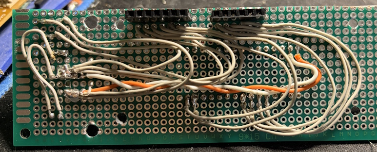
Once working, I reached into my electronics inventory and created a PCB to mount everything. I typically use a PCB design program to play with the spacing so that I’m sure I’m utilizing the PCB correctly. I kept some space for mounting hardware as there there were some nice mounting brackets (I also added the electrical tape as the LCD wasn’t as wide).
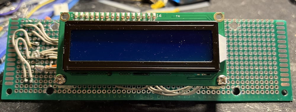
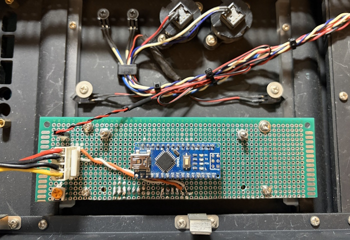
Here are a few more shots of the PCB.
 |
 |
 |
I was able to also wire in the blue front LED’s with a header and also used a quick disconnect for power.
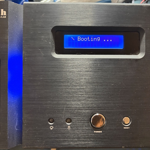
Here is the final result. As you can tell from the code, the micro-controller will start with the “Booting…” as well as a spinning animation.
To make things more useful (and since I have a USB input), I setup a serial input to the code so that I could “push” out display updates. I then used the below Python script on the PC side to push out CPU and RAM updates.
#!/usr/bin/env python3
"""
System Monitor: CPU & Memory Usage to Serial Port
Sends formatted data periodically to a serial port.
"""

import psutil
import serial
import time
import json
from datetime import datetime

# ================= CONFIGURATION =================
SERIAL_PORT = 'COM3'        # Windows: 'COMx' | Linux/macOS: '/dev/ttyUSB0' or '/dev/ttyACM0'
BAUD_RATE = 9600            # Common: 9600, 115200
UPDATE_INTERVAL = 1.0       # Seconds between updates
# ================================================

def get_cpu_usage():
    """Return CPU usage as percentage (per core and average)."""
    per_cpu = psutil.cpu_percent(percpu=True, interval=1)
    avg_cpu = psutil.cpu_percent(interval=None)  # Overall average
    return avg_cpu, per_cpu

def get_memory_usage():
    """Return memory stats in MB."""
    mem = psutil.virtual_memory()
    total = mem.total / (1024 ** 2)
    used = mem.used / (1024 ** 2)
    available = mem.available / (1024 ** 2)
    percent = mem.percent
    return total, used, available, percent

def main():
    print(f"Opening serial port {SERIAL_PORT} @ {BAUD_RATE} baud...")

    ser = serial.Serial(SERIAL_PORT, BAUD_RATE, timeout=1)
    print(f"Connected to {SERIAL_PORT}")

    print(f"Monitoring started. Sending data every {UPDATE_INTERVAL} seconds...")
    print("Press Ctrl+C to stop.\n")

    while True:
        avg_cpu = get_cpu_usage()[0]
        mem_percent = get_memory_usage()[3]

        cpu = [{
            "col": 1,
            "data": f"CPU: {avg_cpu:5.1f}%"
        }]

        mem = [{
            "col": 2,
            "data": f"   MEM: {mem_percent:5.1f}%"
        }]

        # Send to serial
        ser.write(json.dumps(cpu).encode('utf8'))
        time.sleep(.5)
        ser.write(json.dumps(mem).encode('utf8'))
        ser.flush()

        time.sleep(UPDATE_INTERVAL)

if __name__ == "__main__":
    main()
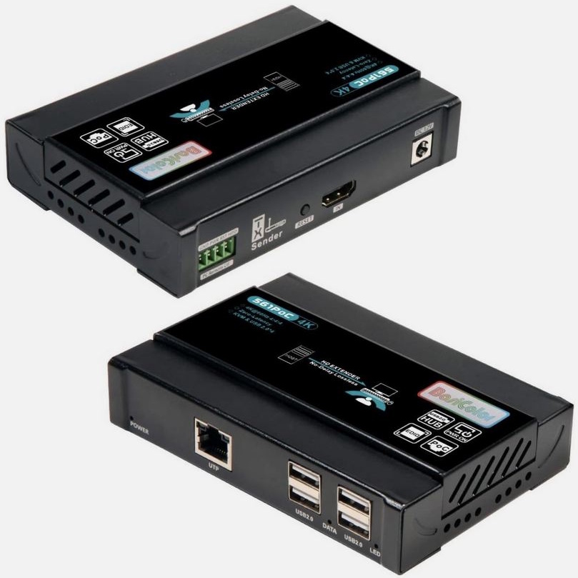
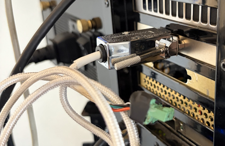
| In my new house, I wanted the ability to run my gaming PC in a separate room and play from it anywhere in the house. First, I had to find a device to accomplish that task. I did find alot of IP KVM extension type solutions, but I felt that would introduce too much latency. Fortunately, I found these KVM extension devices, which use CAT6 to connect, point-to-point. A bonus is these extensions also have PC control, which I quickly rigged up a DB9 connector on the PC side to connected to the host side and a break-out for the remote side, as you can see here. | ||
 |
 |
 |
|
Now, I realize I can just manually move cables, but I wanted to be able to switch rooms without moving cables. My first thought was a manual physical switch, which I found one like the below one on Amazon. |
||
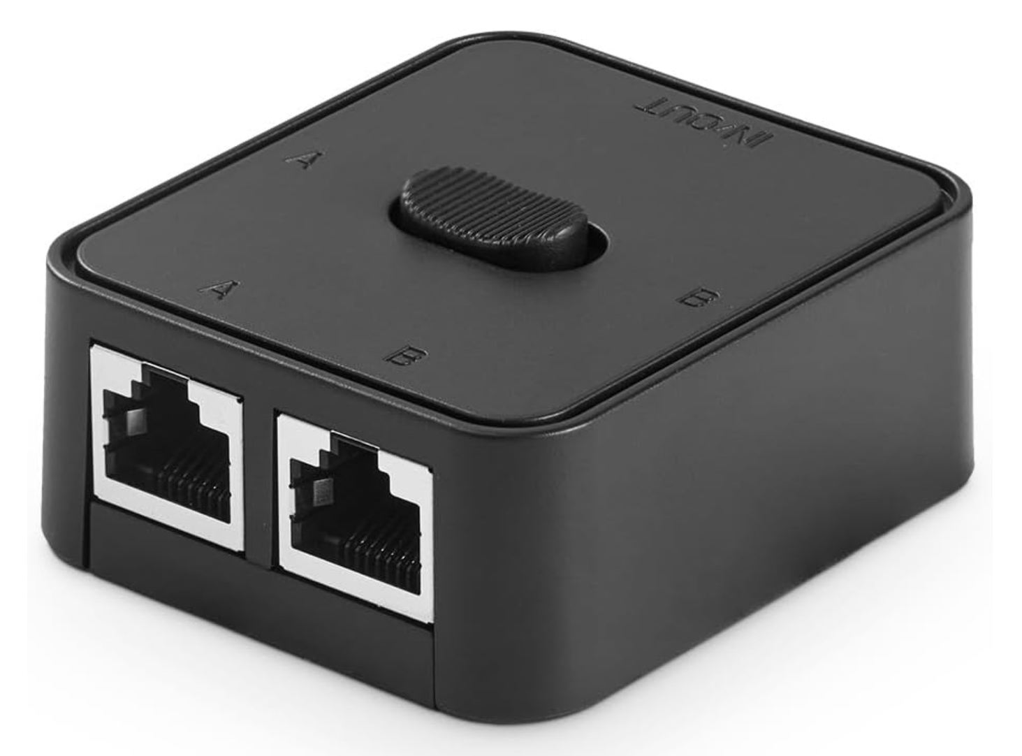 |
My brain then went immediately on how to automate that top switch, so I can switch it via software. I knew I needed something with GPIO and wireless connectivity. I’m quite familiar with the Raspberry Pi but wanted something that I didn’t need to maintain on OS. With that I remembered the ESP32 micro-controller like this one I sourced from Micro Center | 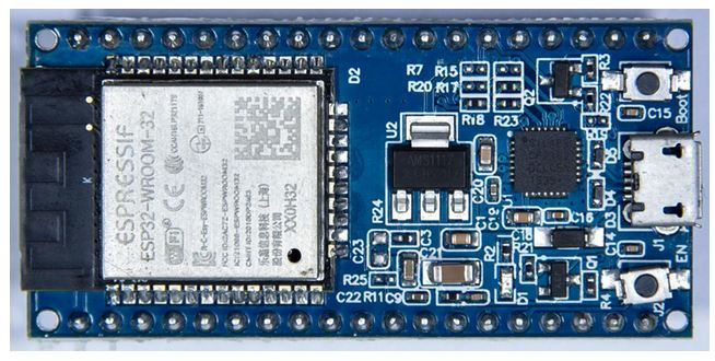 |
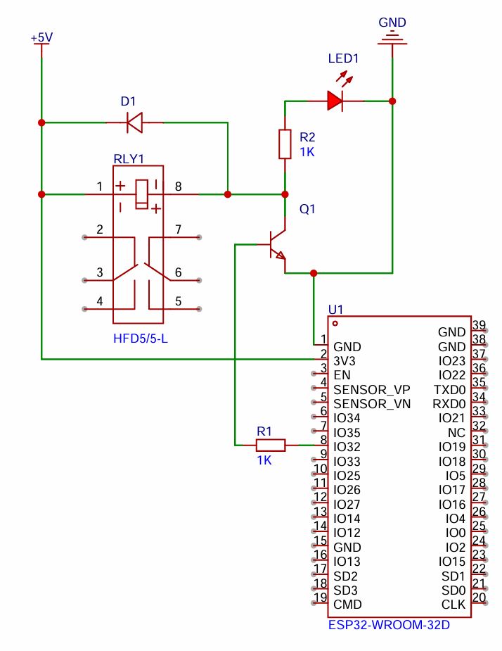
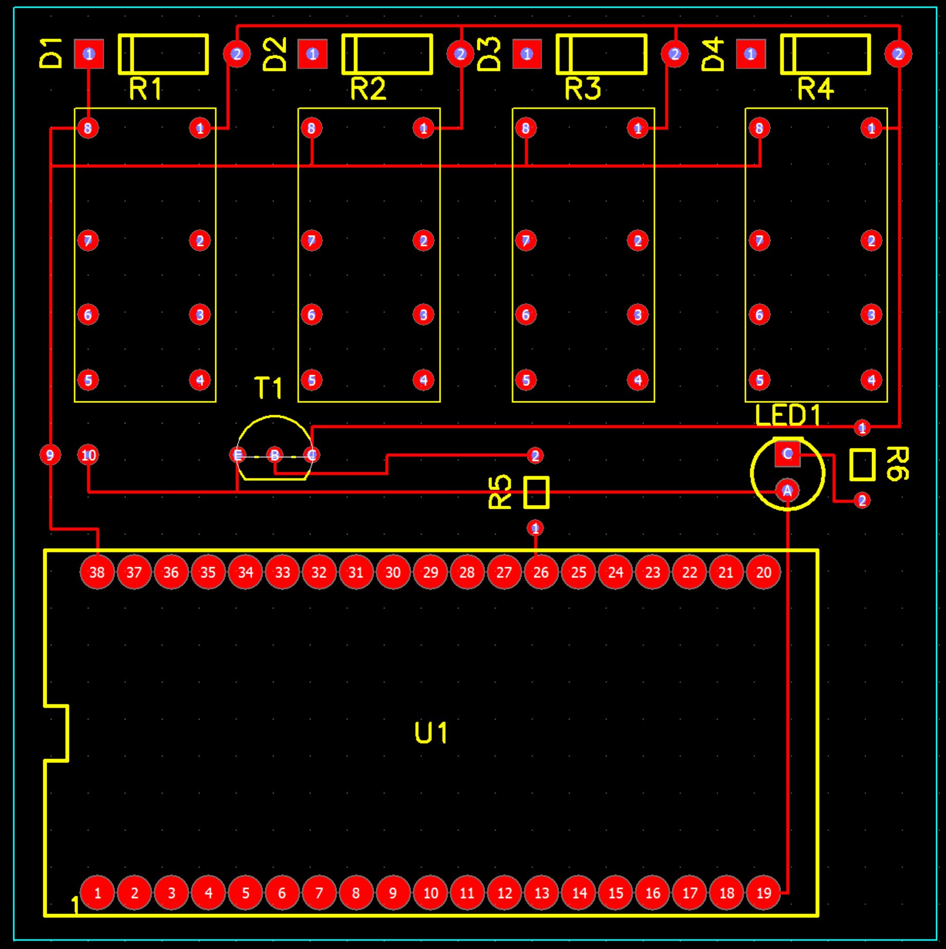
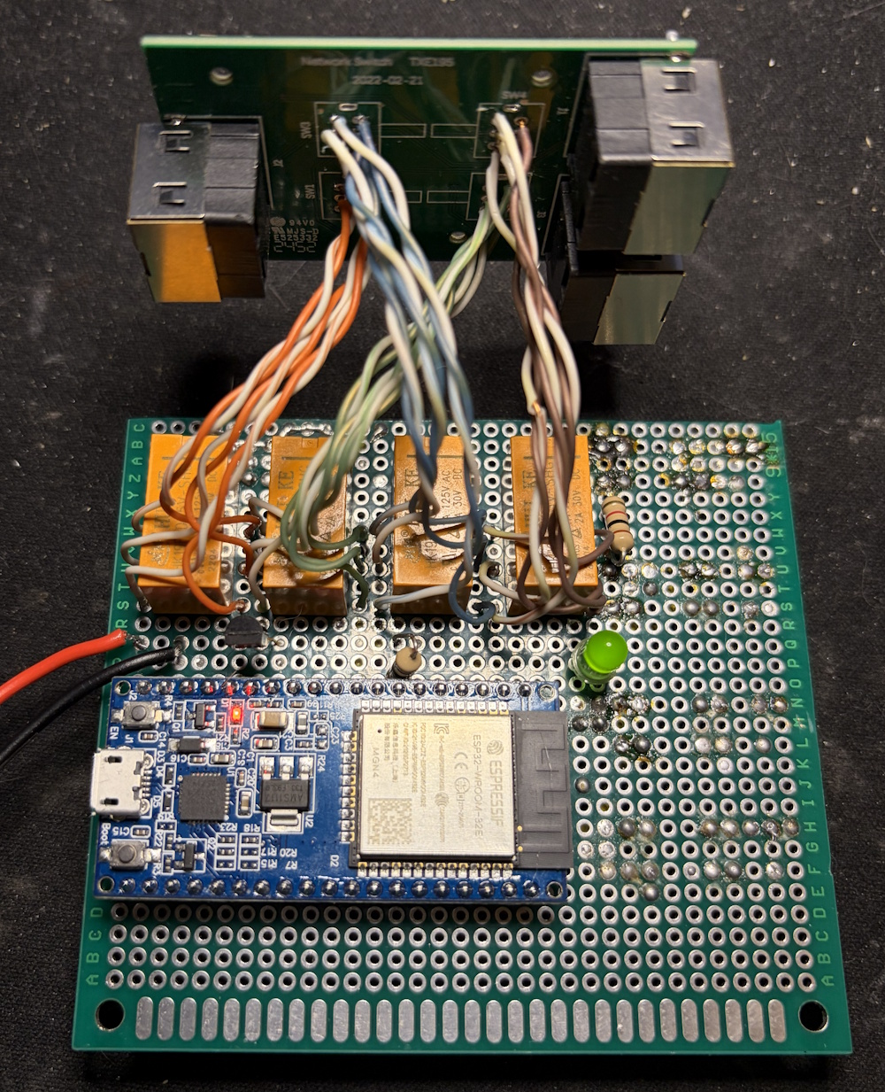
The CircuitFrom research, I found that the voltage on the GPIO pins (3.3v) isn’t enough to switch the relay. To overcome this limitation, I used the classic NPN transistor activation method, so I could use my main 5-volt input as the voltage that switches the relay. The circuit diagram to the left is for one relay, but for this project I just added on the additional three relays since I need to switch all the connection on the switch at the same time. After finished and tested the design on a breadboard, I then found a random piece of PCB prototype board and then used its dimensions in my PCB design software (Pad2Pad) so that I can effectively lay everything out and have enough room without guessing. |
 |
 |
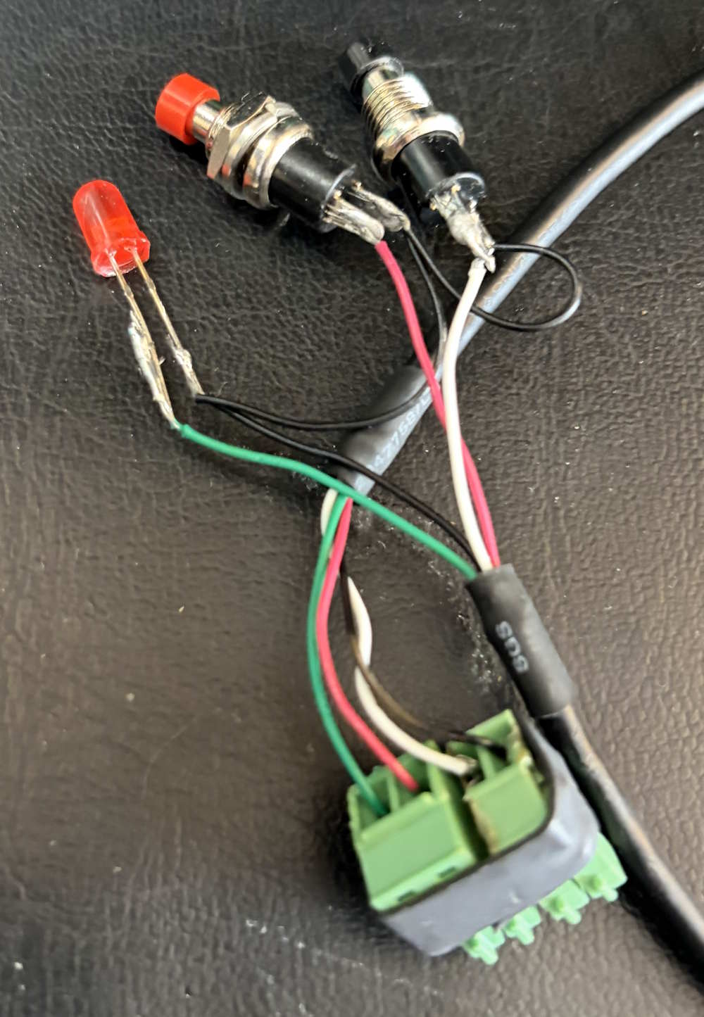
Some additional work I had to do was map out the pinout for both the switch on my CAT6 switching device and the relays I had. I just used my multi-meter and toned out the connections. A concern I did have was if running though this device, there would be any degigation to the signal. The best I could do is make sure anything going from the relay to the swithcer maintaned the twists. |
|
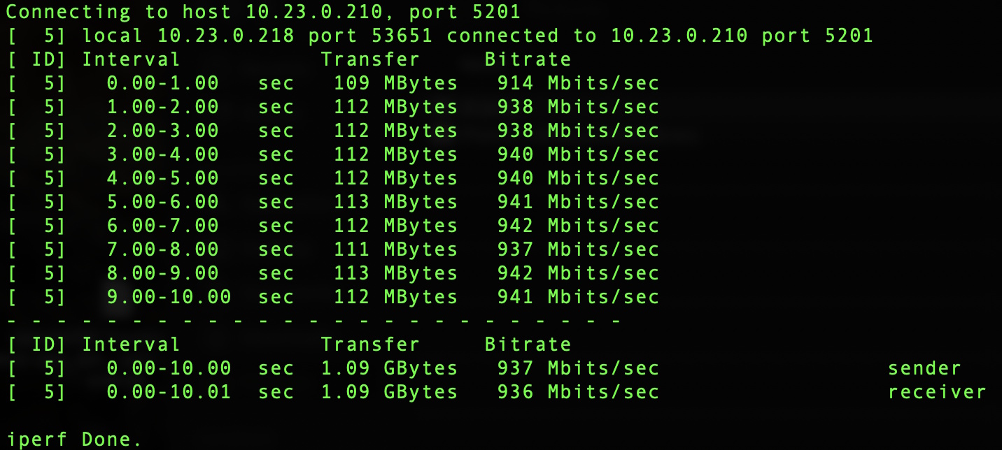
Once I had all the soldering done, I was good to test. For this I used a network tester and made sure the pinout was correct for Ethernet. My next test was to actually get network communication going though the device and see if there was any drop to performance indicating interfearance. Since I am a bit of a network engineer, I opted to use iperf3 and compare with and without the switcher inline. As you can see below I didn’t have any degration at all and was in normal range. |
 |
 |
Now that I knew networking wasn’t affected, I then tested the actual KVM extender to validate I don’t see any video problems or latency. To my satisfication I didn’t notice anything. |
|
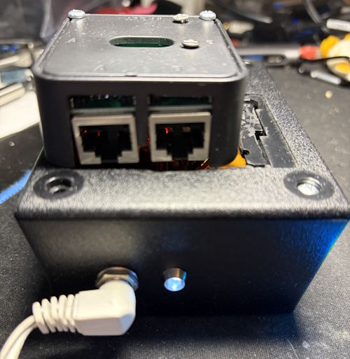
The final build just involved using a project box and mounting the existing switcher on the top. I also added a power LED so I know it’s powered. I had to use my Dremel on some spots to make things fit and it came out okay. Since it’s in a closed room, I wasn’t too concerned on looks.
|
|
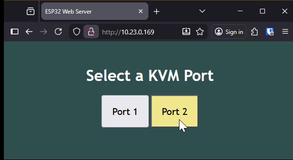
The Code and OutputThe code I pieced together from AI queries. I did put the most work getting the authentication working and customizing the webpage. The downside with a low power micro controller is you cannot use encryption, meaning any password I pick is going across the network in clear text. In my use case, not a big deal as it’s for home use!
As you can see the interface is simple and to the point. It’s fun to hear the relays click when you click the buttons! Anyway, here is the code I am using. #include <WiFi.h>
#include <AsyncTCP.h>
#include <ESPAsyncWebServer.h>
const char* ssid = "";
const char* password = "";
const char* customHostname = "ESP32-NET-SW";
const char* http_username = "admin";
const char* http_password = "admin";
const int output = 32;
// HTML web page
const char index_html[] PROGMEM = R"rawliteral(
<!DOCTYPE HTML><html>
<head>
<title>ESP32 Web Server</title>
<meta name="viewport" content="width=device-width, initial-scale=1">
<style>
body {
font-family: 'Trebuchet MS';
text-align: center;
margin:0px auto;
padding-top: 30px;
background-color: darkslategrey;
color: white;
}
.button {
font-family: 'Trebuchet MS';
padding: 20px;
font-size: 20px;
}
.button:hover {
background-color: khaki;
.button:active {
background-color: #1f2e45;
}
</style>
</head>
<body>
<h1>Select a KVM Port</h1>
<button class="button" onmousedown="toggleCheckbox('off');" ontouchstart="toggleCheckbox('off');">Port 1</button>
<button class="button" onmousedown="toggleCheckbox('on');" ontouchstart="toggleCheckbox('on');">Port 2</button>
<script>
function toggleCheckbox(x) {
var xhr = new XMLHttpRequest();
xhr.open("GET", "/" + x, true);
xhr.send();
}
</script>
</body>
</html>)rawliteral";
void notFound(AsyncWebServerRequest *request) {
request->send(404, "text/plain", "Not found");
}
AsyncWebServer server(80);
void setup() {
Serial.begin(115200);
WiFi.setHostname(customHostname);
WiFi.mode(WIFI_STA);
WiFi.begin(ssid, password);
if (WiFi.waitForConnectResult() != WL_CONNECTED) {
Serial.println("WiFi Failed!");
return;
}
Serial.println();
Serial.print("ESP IP Address: http://");
Serial.println(WiFi.localIP());
pinMode(output, OUTPUT);
digitalWrite(output, LOW);
// Send web page to client
server.on("/", HTTP_GET, [](AsyncWebServerRequest *request){
if(!request->authenticate(http_username, http_password))
return request->requestAuthentication();
request->send(200, "text/html", index_html);
});
// Receive an HTTP GET request
server.on("/on", HTTP_GET, [] (AsyncWebServerRequest *request) {
digitalWrite(output, HIGH);
request->send(200, "text/plain", "ok");
Serial.print("On");
});
// Receive an HTTP GET request
server.on("/off", HTTP_GET, [] (AsyncWebServerRequest *request) {
digitalWrite(output, LOW);
request->send(200, "text/plain", "ok");
Serial.print("Off");
});
server.onNotFound(notFound);
server.begin();
}
void loop() {
// put your main code here, to run repeatedly:
}
|